CAD Automation · Aug 2026

A generator for pipe reducers that outputs real, weldable geometry.

I needed eccentric reducer models for a project and couldn't find a decent free source — most of what's out there is a handful of sizes, the wrong wall thickness, or a mesh pretending to be a solid. So I built the thing I couldn't find: a script that takes an inlet size, an outlet size, a schedule, and a type — concentric or eccentric — and produces a genuine B-rep solid, exported as STEP. Every dimension is sourced and cited, not guessed, and the output has been checked against real manufacturer parts, not just trusted on faith.

128parts generated across concentric + eccentric, 0 geometry failures
3real McMaster-Carr STEP files checked against — matched within the agreed tolerance
10–34 mmstraight-hub length measured on real parts — no single value holds across sizes, and that's stated, not hidden
±12%pressure-rating tolerance, driven by ASME's mill-tolerance allowance, not measurement slop
Method

Two shapes, two different ways to build a solid.

ConcentricOne revolve

A concentric reducer is a body of revolution, so it's built as a single revolve of a profile around the centerline. That's not just simpler — it's exact: the cone and cylinder surfaces come out as genuine analytic geometry (CONE, CYLINDER in the STEP file), not an approximation.

EccentricLoft, then cut

An eccentric reducer isn't axisymmetric — there's no single axis to revolve around. It's built as a loft between offset circles, cut from a matching hollow loft. The transition surface comes out as a NURBS patch, not a cone — there's no single apex point the ruling lines share.

SourcingEvery dimension cited

Pipe OD/wall (ASME B36.10M/19M) and reducer length (ASME B16.9) live in separate, cross-checked tables, joined by size and schedule. Nothing is typed in from memory — every row carries its source, down to the exact page or dataset it came from.

How it got built

Co-built, one phase at a time — bugs included.

This wasn't written in one pass. It went through gated phases — prove the toolchain, one hardcoded part, real dimension data, the generator, validation against real parts, a pressure rating, geometry sanity checks — each one checked before moving to the next. A few of the real mistakes caught along the way, because they say more about how the kernel actually works than the finished code does:

What's inside

Flow through the taper, visualized.

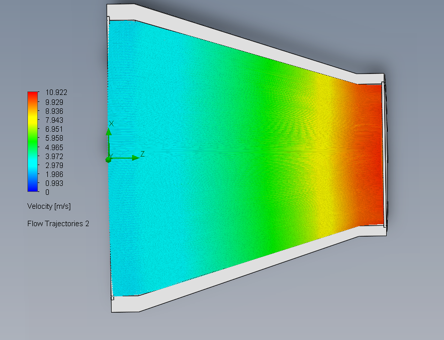
Concentric: velocity climbs as the bore narrows

SolidWorks Flow Simulation cut plot showing velocity increasing smoothly from the large end to the small end of a concentric reducer, blue to red

Continuity says it has to: as the flow area shrinks, velocity rises to match. This is exactly that — a clean, smooth gradient from ~1 m/s at the large end to ~11 m/s at the small end, no surprises.

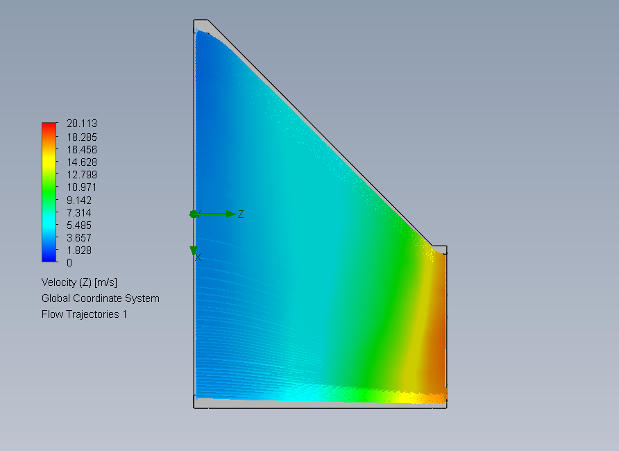
Eccentric: the flush side changes the picture

SolidWorks Flow Simulation cut plot of an eccentric reducer showing velocity concentrated near the flush-side corner rather than distributed evenly

Same idea, different shape. The eccentric offset that makes one side "flush" (see the limitations below) also means the flow doesn't accelerate evenly across the cross-section — velocity concentrates toward one corner instead of the smooth, centered gradient the concentric part shows.

Worth being honest about what these are: default-mesh, first-pass runs meant to show the shape of the physics, not a validated CFD study. Good for the picture, not for citing a specific number.

Try it

Pick a size, see it, download it.

Every combination here is one of the 128 real parts from the library above — not a live, unchecked computation. The viewer mesh is for looking; the actual CAD deliverable is the STEP file the download button gets you.

Large OD (mm)
Small OD (mm)
Length (mm)
Rated pressure (MPa)
Download STEP

Disclaimer

What this doesn't cover — on purpose, not by accident.

Worth being precise about what this section is and isn't. Within what the generator actually models, nothing here has been found wrong — every OD, wall, and offset checked against a real manufacturer part matched, and volume/mass landed inside the tolerance agreed before looking. What follows is scope: things deliberately left out because no reliable source exists for them yet, and a statement about fabrication-readiness — not a list of mistakes.

These models are for layout and reference only. Verify against the governing standard (ASME B16.9, B31.3, and the applicable material spec) before using any of this for fabrication or pressure service. This is student work, not a certified engineering deliverable.

Get it

Code, library, and the full audit trail.

128 STEP files, a manifest with sourced inputs and a SHA256 per file, and everything needed to regenerate the library yourself.